Glory Rail delivered a complete Mobile Harbor Crane Rail System – including DIN 536 A100 rail, W220 clips, chemical anchors, and leveling bolts – for a 300t crane at Jakarta Port. The client’s own local installation team completed the work using only our drawings and step‑by‑step guidance, with no on‑site supervision.
1. Project Background & Challenge
1.1 Project Overview
- Location: Jakarta Port, Indonesia
- Date: November 2025
- Core equipment: 300t lifting capacity mobile harbor crane (with container spreader)
- Application: Vertical container lifting at a backup berth in a large container terminal – high load, high duty cycle, requiring exceptional rail smoothness and stability.
- Client model: The client used their own local civil/installation team for site work. Glory Rail acted as equipment and material supplier only.
1.2 Main Challenge
The main challenge was cross‑border supply coordination:
- Glory Rail supplied only the rail system (shipped from Tianjin to Jakarta). Installation was done by the client’s own third‑party team.
- How to ensure that a remote team in Indonesia could correctly interpret the design intent, follow installation procedures, and avoid rework?
- How to guarantee that 300m of rail would meet the strict straightness, level, and gauge tolerances required by a 300t crane (high wheel loads, significant lateral forces)?
1.3 Our Value
Glory Rail delivered more than just components – we provided a remote‑executable, low‑error installation solution:
- Fully dimensioned drawings with clear annotations.
- Written work instructions and a quality control checklist.
- A proven “adjust‑then‑fix” mechanical leveling method.
Result: The client’s local team completed installation independently and passed final inspection on the first attempt.
2. Scope of Supply & Product List
2.1 Supplied Materials
| Item | Description | Quantity / Length | Notes |
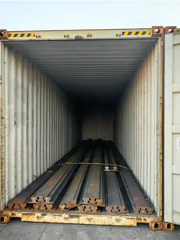
| 1 | A100 Crane rail | DIN 536 A100 300 m | European standard heavy rail, suitable for large‑capacity cranes |
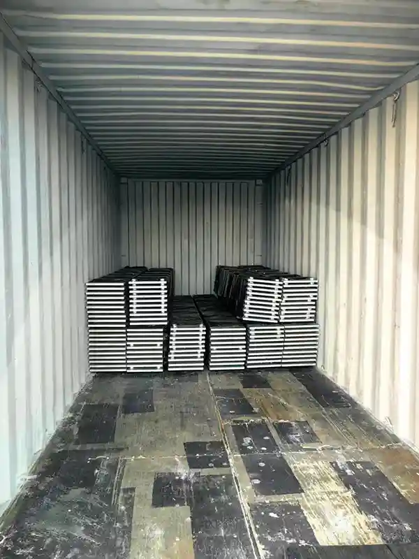
| 2 | Continuous steel base plate | 360mm × 20mm For 300 m | Pre‑drilled holes at standard spacing |
| 3 | W220 rail clips | Weld‑type Approx. 1,200 sets | Installed every 500mm, includes fasteners |
| 4 | Rubber rail pad | 7x195x12000mm 300m | Cushioning, reduces impact load |
| 5 | Anchor bolts (chemical anchors) | M20×300 Matching quantity | For pull‑out / shear resistance |
| 6 | Leveling bolts | M16 Matching quantity | For fine adjustment of height and level |
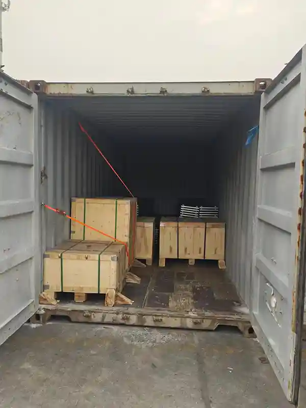
2.2 Logistics Information
- Loading port: Tianjin Port, China
- Destination port: Jakarta Port, Indonesia
- Shipment date: Early November 2025
- Status: Arrived on time, no damage, standard ocean‑worthy packaging
3. Core Technical Solution & Drawing Interpretation
3.1 Overall Structural Concept
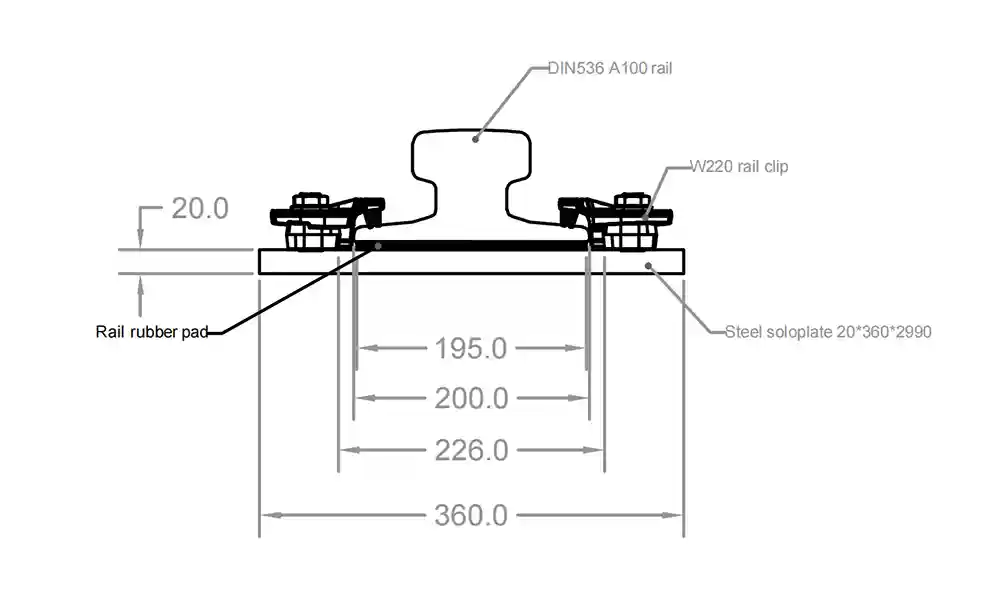
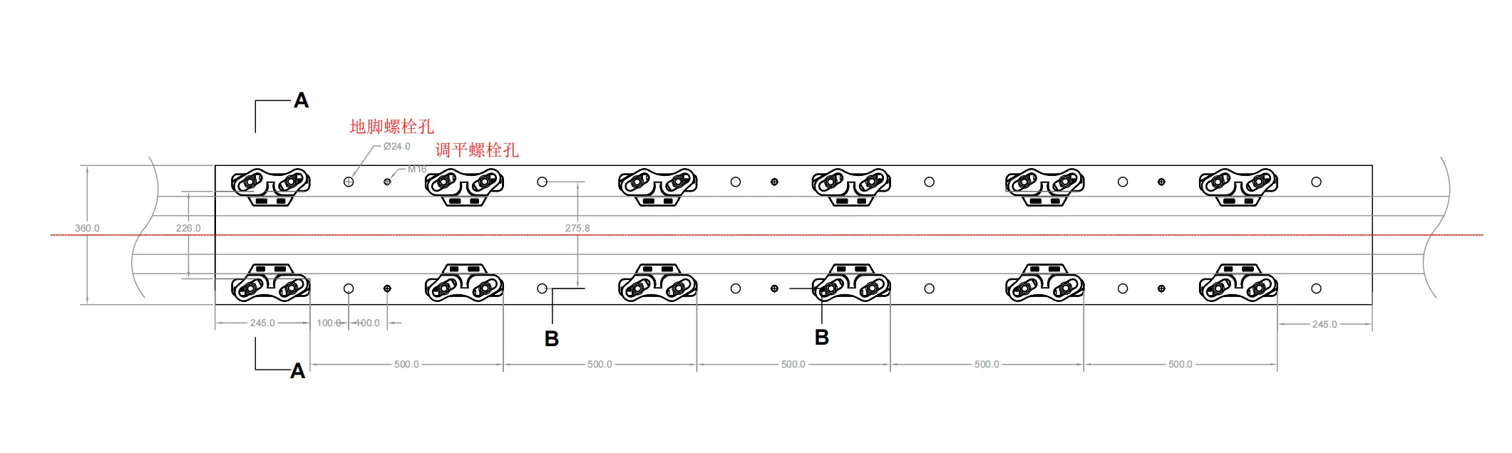
- Offset rail positioning: Distance from rail center to base plate edges: 226mm and 275.8mm (total plate width 360mm). This offset matches the load distribution of the existing concrete foundation, transferring wheel loads efficiently and avoiding local stress concentration.
- Steel base plate + rubber pad: 20mm steel plate spreads the concentrated load; 7mm rubber pad provides elastic cushioning, reduces hard impact, lowers fatigue damage and noise.
3.2 Rail Fixing & Anti‑Shift Design (Section A‑A)
Key points:
- W220 rail clip: Installed symmetrically on both sides of the rail, every 500mm along the rail; first clip 245mm from each rail end.
- Function: Clamps the rail foot, effectively limits lateral movement and lifting of the rail. Prevents “track shifting” or “rail overturning” under a 300t crane.
- Stack‑up (bottom to top):
Concrete foundation → steel base plate (20mm) → rubber pad (7mm) → DIN 536 A100 rail → W220 clip (tightened over rail foot) - Key dimension: Base plate width 360mm. Distance from rail center to plate edge: 195mm / 200mm / 226mm (refer to drawing for exact side).
3.3 Precision Leveling & Permanent Fixing (Section B‑B)
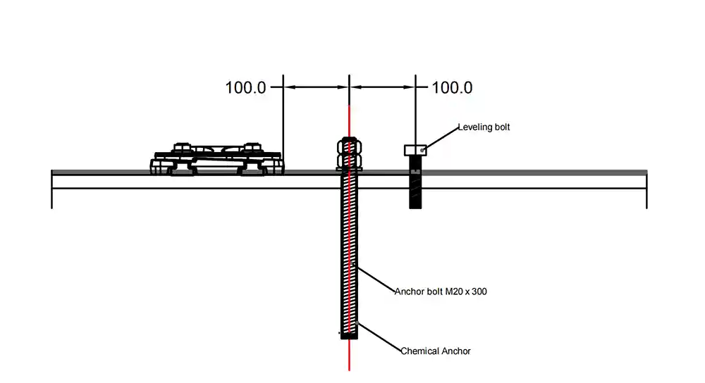
“Adjust‑then‑fix” procedure:
- Use M16 leveling bolts to roughly adjust the height and level of the steel base plate.
- Place rubber pad and rail, install rail clips.
- Fine‑tune height and level again using the leveling bolts with a precision level.
- When correct, tighten the M20 anchor bolts (chemical anchors) for permanent fixing.
Chemical anchor installation requirements (must follow):
Drill hole → clean hole → inject adhesive → insert M20 bolt → allow curing per product data → perform pull‑out test
4. Installation Instructions for the Third‑Party Team
This section is written specifically for the client’s local installation team. Follow it carefully.
4.1 Before Installation
- Check concrete base strength (must meet chemical anchor requirements, ≥ C30 recommended).
- Prepare tools: precision level, torque wrench, rotary hammer (Ø24 bit), hole cleaning tools, adhesive injection gun.
- Lay out lines on concrete: mark rail center line, clip center points every 500mm, and bolt hole positions.
4.2 Main Installation Steps
| Step | Action | Notes |
|---|---|---|
| 1 | Position base plates | Place base plates per plan view, insert anchor bolts (M20) and leveling bolts (M16), do not tighten yet |
| 2 | Rough leveling | Use leveling bolts to bring plate top surface close to design height (deviation ≤2mm per meter) |
| 3 | Place rubber pads & rail | Rubber pads must be flat, undamaged, oil‑free; center the rail on the pads |
| 4 | Install rail clips | Start from one end, install W220 clips every 500mm (245mm from ends). Tighten symmetrically to recommended torque |
| 5 | Fine level & final fix | Fine‑level with precision instrument → final tighten anchor bolts (after adhesive curing time) → apply thread‑locker to leveling bolts |
4.3 Quality Control Checklist
Check each item and sign off:
- Rail centerline straightness ≤ 2mm per 10m (check with string line or laser)
- Top surface level difference between two rails ≤ 3mm at any cross‑section
- Pull‑out test for chemical anchors: 100% pass (sampling per standard – e.g., 10% of all anchors)
- Rail clip torque: All W220 clips tightened to the same recommended torque (typically 120 Nm, verify with product data sheet)
- Leveling bolt locking: Thread‑locker applied and lock nut tightened
5. Project Outcome & Value Summary
5.1 Successful Delivery
- 300m DIN 536 A100 rail and all accessories shipped from Tianjin Port in early November 2025, arrived at Jakarta Port on time and in perfect condition.
- Complete technical drawings and work instructions provided in English (and Chinese as reference).
5.2 Hassle‑Free Installation
- The client’s third‑party installation team followed Glory Rail’s drawings and written instructions independently.
- First‑time pass of final inspection – straightness, level, and clip torque all met design requirements.
5.3 Client Feedback
“Your technical documentation made a cross‑border installation feel like local work. Even without a field engineer, our team understood every requirement clearly.”
– Project manager, Indonesian client
5.4 Operational Performance
The mobile harbor crane is now working at the backup berth, performing smooth, efficient vertical container lifting. After heavy load testing and continuous operation, the rail system shows no abnormal settlement, shifting, or loose clips.
6. Conclusion
This case clearly demonstrates Glory Rail’s capability in overseas heavy‑duty crane rail system supply:
- Product: A100 rail and full set of high‑reliability accessories, meeting DIN standards.
- Logistics: Smooth international shipping from Tianjin to Jakarta – on time, no damage.
- Technical: Detailed drawings and remote‑executable instructions allow the client’s own installation team to achieve high‑precision construction without on‑site support.
Glory Rail does not just “sell rail” – we provide a complete Mobile Harbor Crane Rail System solution, especially suited for overseas projects where the client handles installation and needs remote technical support.
For similar projects, contact Glory Rail. We offer one‑stop service from design and supply to remote installation guidance.