
The A120 Rail System for Shipyards must withstand the wheel loads of large cranes, the forces generated by frequent operation, and the effects of salt fog and humidity in the marine environment. In addition to the rails themselves, the fastening methods, anchor bolts, support plates, and corrosion protection measures directly affect the operational stability of the entire system.
Drawing on specific A120 rail projects, this article outlines the key technical requirements for fastening, anchoring, rubber pads, and corrosion protection in heavy-duty crane rail systems for shipyards and dry docks.
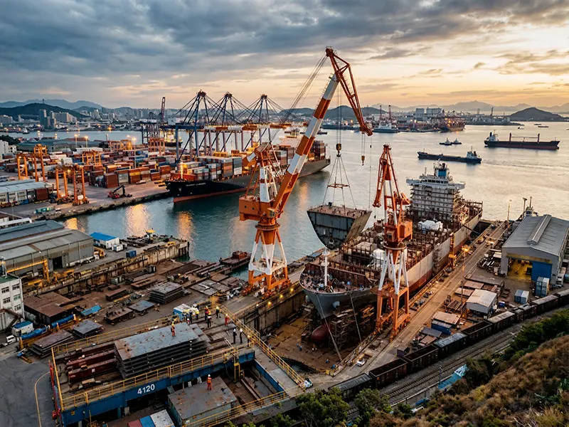
1. Design Considerations for Shipyard Crane Rail Systems
Shipyard gantry cranes typically operate under heavy loads and in highly corrosive environments; therefore, the design of rail systems must prioritize the following factors:
- Wheel Loads: High wheel loads exert significant vertical forces on the rails and supporting structures.
- Lateral Forces: Horizontal forces generated during crane operation and braking must be absorbed by the fastening system.
- Rail Alignment: Rail alignment and the condition of rail joints affect wheel contact and operational stability.
- Foundation Support: The foundation must possess sufficient strength and stiffness to safely transfer loads.
- Corrosion in Marine Environments: Salt fog, humidity, and outdoor exposure accelerate the corrosion of steel components.
These factors must be comprehensively considered in conjunction with the actual crane loads, track layout, and operating environment; fastening and foundation solutions cannot be determined solely based on the rail type.
2. Selection of Fastening Methods for A120 Rails
The fastening system is responsible for securing the rails to the support structure and withstanding the forces generated during crane operation. Common fastening methods for heavy-duty crane tracks include bolted and welded rail clamps.
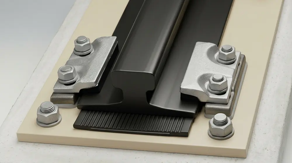
Bolted and Welded Rail Clamps
| Consideration | Bolted Rail Clamps | Welded Rail Clamps |
|---|---|---|
| Connection method | Bolted connection | Welded connection |
| Installation adjustment | Generally easier to adjust | Depends on the welded arrangement |
| Supporting structure | Depends on clamp design | Requires a steel supporting plate |
| Main design consideration | Bolt capacity and fastening stability | Plate thickness and welding requirements |
Bolted clamps are suitable for heavy-duty track systems designed with adequate load-bearing capacity. For shipyard tracks using continuous steel backing plates, welded clamps may also be considered if a more rigid connection is required.
When using welded connections, the following must be carefully inspected:
- Soleplate thickness and structural load-bearing capacity;
- Welding methods, weld dimensions, and welding materials;
- Whether the welds can withstand the forces exerted by the fastening system;
- Whether construction is carried out in accordance with approved welding procedures.
Welded clamps cannot be installed directly on concrete foundations; they must be supported by a suitable steel support structure.
Function of Steel Soleplates
Steel soleplates provide a support surface for the rails and also serve as the connection base for fastening components.
Their design primarily considers plate thickness, structural stiffness, load transfer, rail adjustment space, as well as corrosion protection and welding requirements. If the soleplate lacks sufficient stiffness, it may affect rail support and fastening performance; therefore, dimensions must be determined based on actual loads and the installation plan.
3. Design and Foundation Requirements for A120 Rail Anchor Bolts
Anchor bolts are used to secure rail clamps or support plates to the foundation and to transfer the forces exerted on the rail system to the concrete structure.
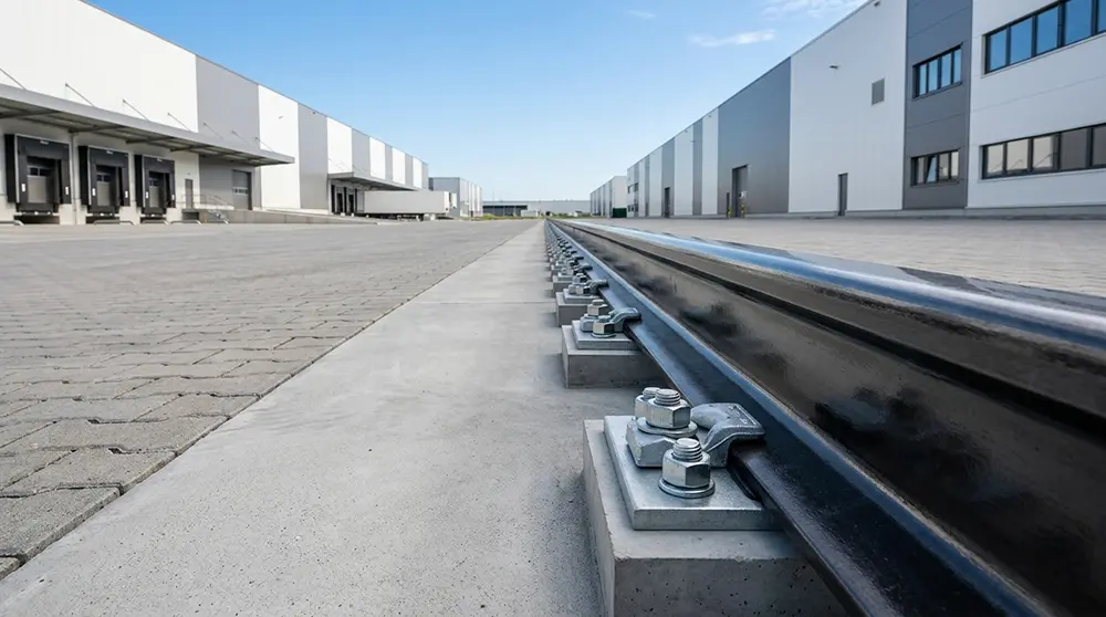
Loads and Embedment Depth of Anchor Bolts
In a typical installation, loads are transmitted through the rail, fasteners, and support structure to the concrete foundation. Anchor bolts may be subjected to tensile forces, shear forces, or a combination of both; therefore, they must be designed based on the actual connection loads.
The embedment depth primarily depends on:
- Concrete strength;
- Bolt diameter and material strength;
- Actual tensile and shear forces;
- Bolt spacing and edge distances;
- Foundation dimensions and anchorage structure.
In the shipyard project described in this article, the A120 rail system utilized an anchor bolt embedment depth of 260 mm.
It should be noted that this is a design parameter specific to this project and is not a universal requirement for all A120 rail installation projects. The final embedment depth should be determined through anchorage calculations, while also verifying the bolt’s own strength and the concrete’s anchorage bearing capacity.
The total length and weight of the anchor bolts also depend on the embedment depth, the exposed length, and the end anchorage structure; therefore, sample data from this project cannot be directly used as a universal specification.
4. Rail Rubber Pads: Load Distribution and Vibration Control
Rail rubber pads are installed beneath the rails or support plates according to the system design. They are primarily used to provide elastic support, absorb vibrations and impacts, and reduce direct metal-to-metal contact between the rails and the supporting structure.
Primary Functions and Specifications of Rubber Pads
Rubber pads help distribute loads, protect support surfaces, and improve the contact condition between the rail and the foundation. However, excessive compression deformation or unsuitable material properties may also affect rail alignment and fastening stability.
When selecting a model, the following parameters must be confirmed:
- Material type;
- Hardness and thickness;
- Dimensions;
- Load-bearing capacity and compression performance.
The shipyard project described in this article uses wear-resistant synthetic elastomer rubber pads with a hardness requirement of 75 ±5 Shore A.
This value is a project-specific requirement and does not represent a uniform standard for all rubber pads used on heavy-duty crane rails. Actual selection should also include an assessment of the rubber pad’s compression deformation under working loads.
5. Corrosion Protection for the A120 Rail System in Marine Environments
Salt spray and humid environments can accelerate the corrosion of steel components, particularly steel shims, anchor bolts, and other exposed fasteners. Therefore, appropriate corrosion protection methods should be selected for different components based on their operating environment and actual function.
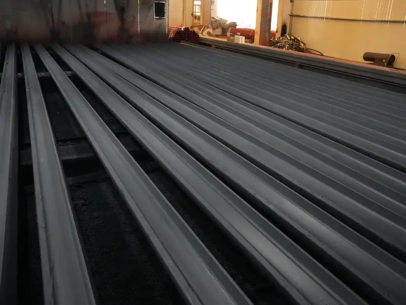

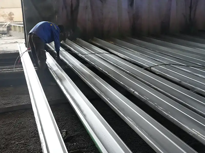
Surface Preparation and Sandblasting Requirements
For steel components requiring painting, proper surface preparation must be performed prior to coating.
The project described in this document requires Sa 2.5-grade sandblasting to remove surface rust and contaminants and to achieve the surface cleanliness and roughness required for coating application.
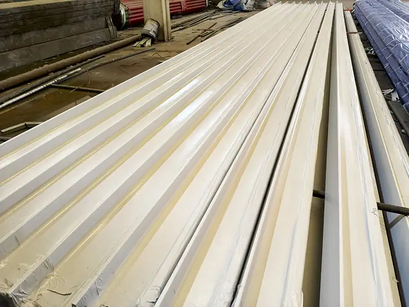
Multi-Layer Corrosion-Resistant Coating System
This project specifies the following Jotun coating system:
| Coating Layer | Project-Specified Product | Dry Film Thickness |
|---|---|---|
| Primer | Barrier 80 Grey | 65 μm |
| Intermediate | Jotamastic 87 Buff | 200 μm |
| Topcoat | Jotamastic 87 Orange | 150 μm |
| Total | Three-layer coating system | 415 μm |
The total dry film thickness for this project is 415 μm. This is a project-specific coating requirement and does not constitute a standardized anti-corrosion solution that must be applied to all A120 rails.
Prior to application, the compatibility of the coatings, surface preparation requirements, and their suitability for the project’s specified corrosion environment must be verified.
The project documentation also references the C5-CX corrosion protection system, which requires a total dry film thickness of at least 250 μm. Specific applicability and complete coating requirements must be further confirmed in accordance with the project specifications.
Hot-Dip Galvanizing of Bolts and Fasteners
Anchor bolts, nuts, washers, and other fasteners can undergo hot-dip galvanizing depending on the corrosive environment, providing corrosion protection through a zinc coating on the surface.
For threaded components, special attention must be paid to coating thickness and dimensional tolerances to avoid affecting subsequent assembly. The corrosion protection method for each component should be determined individually based on its structure and application requirements.
Conclusion
The reliable operation of the A120 Rail System for Shipyards depends not only on the A120 rail itself but is also closely related to the fastening method, anchor bolts, support structures, rubber pads, and corrosion protection measures. A reasonable system configuration must be determined comprehensively by considering crane loads, foundation conditions, and the marine environment.
Glory Rail supplies A120 crane rails compliant with DIN 536 and offers custom cutting, end machining, and matching fastening components. We can also assist in determining the appropriate scope of supply based on the project’s rail layout, fastener drawings, and coating requirements.