
Crane rail miter cutting requires more than achieving a specified cutting angle. The accuracy of the rail ends, the condition of the tread surface, and the fit between adjacent rail sections all affect the quality of the finished joint. For projects requiring 45° miter cuts, controlling the cutting angle within the specified tolerance and preventing tread depressions are essential to maintaining a smooth transition for crane wheels.
This guide explains how 45-degree cutting affects crane rail joints, which machining requirements need attention, and how to inspect rail ends before delivery.
Why Is the Precision of Crane Rail Joints Important?
Rail joints are critical components of the crane track system because crane wheels repeatedly pass over these locations during operation. Poor alignment between the ends of adjacent rails can create localized discontinuities along the wheel’s path.
How Does the Gap at Rail Joints Affect Wheel Operation?
Excessive gaps between adjacent rail ends may cause impact when crane wheels pass over the joints. The actual extent of the impact depends on the wheel load, operating speed, joint gap size, and the geometry of the rail ends.
Repeated impacts may result in:
- Increased vibration during crane operation.
- Localized wear on the wheel tread and rail head.
- Additional dynamic loads on the rail support structure.
- Increased future maintenance requirements.
The joint gap is not the only factor determining joint performance. Rail end alignment, vertical height differences, the condition of the rail clamps, and the stability of the support structure must also be considered.
Why are rail end alignment and tread continuity important?
Even if the rail end cutting angle is correct, improper alignment after installation can still affect wheel operation. The rail heads of adjacent rails must meet specified installation tolerances to avoid significant height differences or an uneven running surface.
Therefore, when evaluating the quality of rail joints, one must not only inspect the cutting angle but also examine the end geometry and the condition of the running surface.
Why Do Crane Rails Require a 45° Miter Cut?
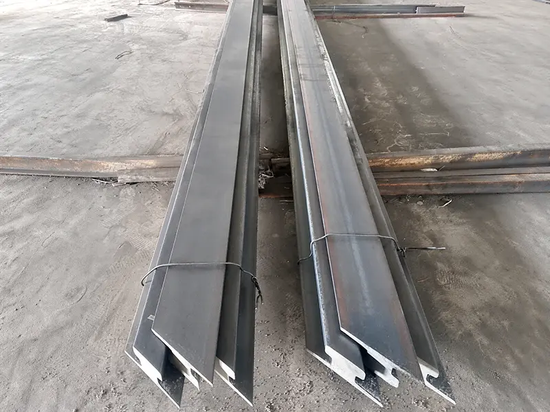
A 45° miter cut creates an angled surface at the rail end rather than a traditional vertical cut. In certain specific rail joint designs, engineering drawings may require this machining method to meet specific end-fit requirements.
Understanding the 45° Miter Cut in Crane Rail Joints
A miter cut refers to cutting the rail end at a specific angle. When two sections of rail are joined, the cutting direction and end profile of both ends must conform to the specified joint design.
It is important to distinguish between miter cutting and standard beveling. Standard beveling typically involves removing a small amount of material from the edge to form a beveled surface, whereas miter cutting alters the entire geometry of the rail end.
A 45° miter cut should not be considered a universal requirement for all crane rail joints. The specific cutting direction, angle reference plane, and joint configuration must all be confirmed based on the engineering drawings.
How does the cutting geometry affect the rail joint clearance?
The cutting angle directly affects the shape of the end and the position of the mating surfaces. If the actual cutting angle deviates from the specified value, the ends of the two rail sections may not fit together as intended.
However, simply ensuring the correct cutting angle does not guarantee a small joint clearance. The following factors must also be controlled:
- Consistency in the cutting direction at both ends.
- Proper positioning and installation orientation of the rails.
- End dimensions that conform to the engineering drawings.
- Accurate alignment between adjacent rails.
The ultimate goal is to meet the specified joint geometry and installation clearance, not merely to achieve a nominal 45° cutting angle.
Key Technical Requirements for Precision Miter Cutting of Crane Rails
When machining crane rails with mitered ends, three aspects warrant particular attention.
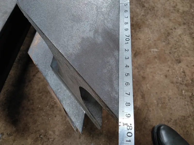
Cutting Angle Tolerance: 45° ±0.5°
The cutting angle tolerance determines the permissible deviation range between the end of the finished rail and the specified angle.
For projects requiring 45° ±0.5°, the actual measured angle must be controlled within the range of 44.5° to 45.5°. If the deviation exceeds this range, the rail end may fail to meet the specified joint geometry requirements.
To maintain machining accuracy, the following must be ensured:
- Establish a clear and consistent cutting reference.
- Securely clamp the rail before machining.
- Use specialized angle fixtures.
- Verify the cutting angle using calibrated measuring tools.
For projects involving the machining of multiple rails, inspecting only the first piece is insufficient. Each finished rail must be inspected in accordance with the quality inspection plan agreed upon by both parties.
How can the flatness of the rail running surface be maintained after a 45° miter cut?
The rail running surface is the surface that comes into direct contact with the wheels of locomotives and rolling stock. Any dents, notches, or unevenness near the cut may result in discontinuities on the wheel running surface.
This is particularly important for 45° miter-cut rails. During the machining process, it is essential not only to achieve the specified bevel geometry but also to avoid damaging the rail head or causing unnecessary material loss on the running surface.
After machining is complete, a visual inspection of the rail head should be conducted. A straightedge or suitable measuring tool may also be used to check for local surface irregularities in accordance with project requirements.
It is important to note that even if the cutting angle meets specifications, this does not necessarily mean the rail end is acceptable. The condition of the running surface must be inspected separately.
How can consistent cutting geometry be ensured across multiple rails?
When a project involves multiple rails, processing consistency is also a critical requirement.
For example, if a project requires the processing of 20 rails, each with beveled ends at both ends, consistent cutting reference points and positioning methods should be used throughout the entire processing procedure.
Inspection items should include:
- Cutting direction and processing position.
- Accuracy of the cutting angles at both ends.
- Length of the processed rail.
- End profile and surface condition.
This helps minimize processing variations between different rails, making subsequent on-site installation easier to control.
How can crane rails be precisely cut at a 45° Miter?
Both the cutting method and positioning equipment affect the final machining quality of the rail ends.
Cutting with a CNC Heavy-Duty Metal Band Saw
CNC heavy-duty metal band saws are suitable for machining large steel cross-sections and are effective in scenarios requiring precise control of cutting geometry.
Compared to oxy-fuel or plasma cutting, mechanical band saw cutting avoids the concentrated heat input associated with thermal cutting processes, helping to prevent the formation of the typical heat-affected zone near the cut.
However, it is still necessary to properly control the cutting speed, saw blade condition, feed rate, and workpiece stability to avoid rough cut surfaces or dimensional deviations.
Using Specialized Angular Fixtures to Ensure Positioning Accuracy
Specialized angular fixtures help secure the rail in the specified cutting direction and angular position.
Their primary functions include:
- Maintaining the specified cutting angle.
- Preventing rail displacement during machining.
- Providing a consistent positioning reference.
- Improving consistency during repeat machining of multiple rails.
For large crane rails, stable workpiece support is particularly important, as both the weight and dimensions of the rails can affect positioning accuracy.
Deburring and Chamfering After Cutting
After completing the miter cut, inspect the cut edges and remove any excess burrs.
Proper edge treatment helps prevent sharp protrusions from interfering with product handling or on-site installation. Chamfering should be performed in accordance with engineering drawings or mutually agreed-upon machining requirements, while ensuring that the specified rail end geometry remains unchanged and the running surface is not damaged.
How to Inspect the Ends of Crane Rails After Miter Cutting?
Final product inspection should not focus solely on the cutting angle but should also cover other key quality indicators. The following checklist can help verify whether the machined rail ends meet project requirements.
| Inspection Item | What to Check | Suggested Method |
|---|---|---|
| Cutting Angle | 45° ±0.5° where specified | Calibrated angle measuring instrument |
| Rail Tread | No depressions or visible cutting damage | Visual inspection and straightedge |
| Cut Surface | No excessive burrs or irregular edges | Visual inspection |
| End Geometry | Matches the supplied drawing | Dimensional measurement |
| Rail Length | Meets the specified dimensions | Calibrated measuring tape |
For projects with strict quality requirements, the inspection plan should also specify measurement references, allowable surface deviations, and inspection frequency.
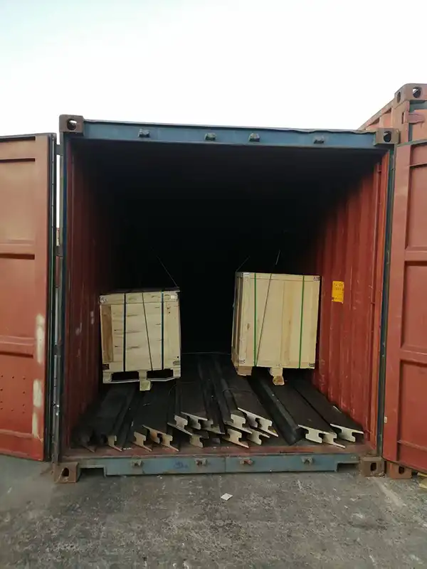
End inspections of the rails should be completed prior to packaging to identify and correct any potential machining issues before shipment.
Case Study: Supply of A100 Crane Rails and 45° Precision Miter Cutting
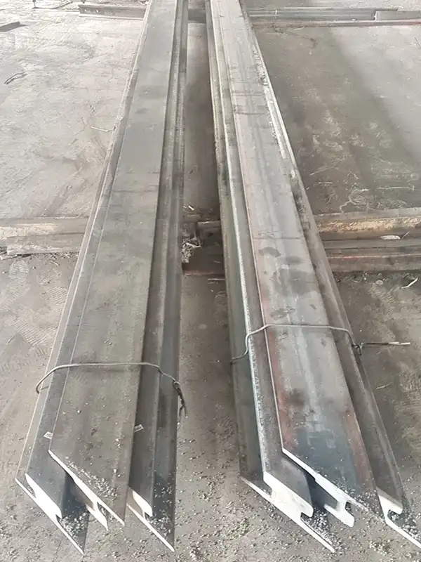
In an A100 crane rail project, the customer requested the procurement of 20 U71Mn rails, each 12 meters long, with both ends mitered at 45° according to the provided engineering drawings.
Key machining requirements included:
- Cutting angle tolerance controlled within ±0.5°.
- No dents were to appear on the rail running surface after miter cutting.
- Consistent end geometry was required to control the joint gap between adjacent rails.
The rails were processed using a CNC heavy-duty metal band saw and specialized angle fixtures. After cutting, the rail ends were deburred and edge-finished, and inspected prior to shipment.
In addition, the project included the supply of 1,000 sets of 9120 rail clamps and 20 rolls of MK7 rubber pads with steel backing plates, which together constitute the track fastening and support system required for the project.
This project demonstrates that custom rail machining must take into account both dimensional accuracy and the condition of the finished running surface. The cutting requirements mentioned above are derived from engineering drawings provided by the customer, rather than the general requirements specified in DIN 536.
Conclusion
Precise end machining of crane rails requires simultaneous control of the cutting angle, end geometry, and running surface condition. The 45° miter must comply with the specified joint design, while proper positioning, mechanical cutting, and post-machining inspection help maintain consistent machining quality.
Glory Rail supplies crane rails in accordance with applicable product specifications and offers custom machining services—including miter cutting, drilling, and cutting to length—based on project requirements. Customers may provide rail types, technical drawings, cutting angles, and inspection requirements for technical evaluation prior to production.