Maintaining a perfectly straight, level, and structural track is the most critical challenge in crane runway installation. Achieving precise crane rail welding joint alignment is essential to prevent severe dip joints, which accelerate wheel wear and cause structural vibrations. This guide outlines the professional procedure for managing thermal distortion, preheating, and grinding to ensure a flawless, long-lasting track system.
Step 1: Pre-Deflection and Mechanical Setup
Proper crane rail welding joint alignment begins long before the arc is struck. To counteract the inevitable downward shrinkage of the cooling weld metal, the rail ends must be pre-deflected upward.
Setting Up the Pre-Elevation
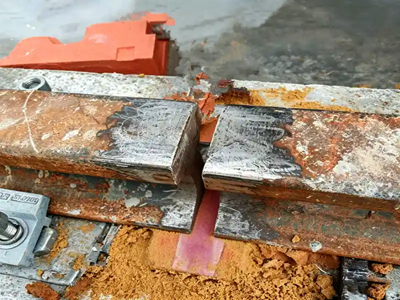
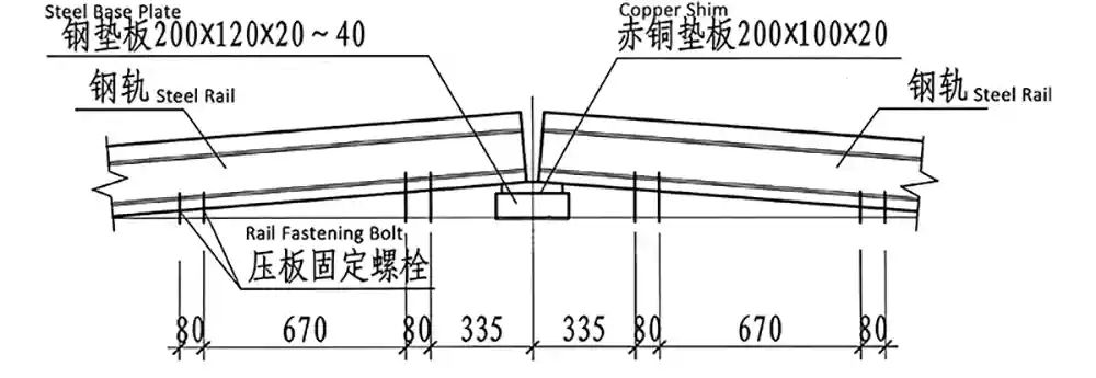
- Initial Elevation: Use copper backing plates and steel shims to jack up the two rail ends by 40 mm to 60 mm.
- Rigid Clamping: Secure the rails using heavy-duty bolts and pressure plates, with at least four clamping points near each joint to maintain structural rigidity.
- The Root Gap: Align the rail ends with a joint gap of 12 mm to 14 mm. Ensure the two rails are perfectly centered along a single axis with zero twisting.
Step 2: Thermal Management (Preheating & Tempering)
Controlled thermal cycles prevent cold cracking and reduce residual stresses. Consistent crane rail welding joint alignment relies on balancing these thermal inputs to prevent erratic warping during the cooling phase.
| Thermal Phase | Target Temperature | Heating Zone | Field Validation Method |
| Preheating | ~250°C | 20–30 mm on both sides | Heated for ~10 minutes (No. 7 nozzle) |
| Tempering | 600°C – 700°C | 40 mm on both sides | Heated to a dull red glow |
Step 3: Multi-Pass Manual Arc Welding Sequence
Achieving optimal crane rail welding joint alignment requires a strict bottom-up deposition sequence: Rail Base → Rail Web → Rail Head.
Consumables and Technique
- Electrode: ø 4.0 mm low-hydrogen basic electrodes (E7515/B7516 or B8515/B8516).
- Polarity: Direct Current (DC), Electrode Positive.
1. Welded Rail Base (Bottom Flange)
Deposit the first bead at 180 A to 200 A for penetration. Reduce to 160 A to 180 A for subsequent passes. Clean slag meticulously after every pass. After finishing the base, lower the pre-elevation shims to 20 mm and re-tighten the clamps to correct the geometry.
2. Welded Rail Web
Remove shims and clamps once web welding begins. Use custom copper backing plates 80 mm wide x 10 mm thick tightly against the web. Deposit weld metal from bottom to top at 150 A to 170 A, removing and cooling the copper plates between electrode changes.
3. Welded Rail Head
Install copper top molds and weld the head at 150 A to 170 A. By maintaining symmetry in layer deposition, you preserve the crane rail welding joint alignment established during the earlier stages.
Step 4: Post-Weld Heat Treatment and Cooling
Immediately after welding, temper the joint zone to 600°C–700°C. Once tempered, wrap the joint in an insulated, slow-cooling box (using an asbestos bottom board and wooden sides). Allow the joint to cool naturally to ambient temperature. Protect the hot joint from moisture, as rapid quenching will cause brittle failures and compromise the structural alignment.
Step 5: Profile Grinding and Finishing
After cooling, restore the rail profile to geometric tolerances. Use a cold chisel to remove excess metal, followed by a hand-held electric angle grinder for flush-finishing. Finally, use fine emery paper to eliminate notches.
By prioritizing crane rail welding joint alignment through every thermal stage—from pre-deflection to the final grinding pass—you can guarantee a perfectly straight runway that ensures smooth crane travel and maximizes the service life of your infrastructure.