Introduction
In the construction of Continuous Welded Rail (CWR), the quality of the welded joint dictates the overall smoothness and service life of the track. While often overshadowed by the welding process itself, rail head beveling—the precise machining of geometric slopes at the rail ends—is a critical prerequisite. A well-executed bevel ensures full penetration, eliminates stress concentration, and accommodates specific welding metallurgy.
This guide breaks down the core functions of beveling, analyzes control dimensions across different steel grades, and identifies the “invisible defects” that can compromise track integrity.
1. Functional Pillars and Control Dimensions
Beveling the rail head is not merely about “cutting a slope.” It requires simultaneous precision across three dimensions to prevent welding failure.
- Geometric Accuracy: For thermit welding, a single-side angle of 60°–70° (totaling a 120°–140° gap) is standard. If the angle is too wide, the excessive filler metal increases the risk of shrinkage cavities; if it’s too narrow, the heat source cannot reach the root, causing lack of fusion.
- Surface Integrity: The machined surface must exhibit a clean, silver-gray metallic luster. “Grinding burns”—blue-purple oxidation layers caused by excessive pressure or blunt tools—act as contaminants. Since these oxides have a higher melting point than the parent steel, they often remain as slag inclusions in the finished weld.
- Root Face (Blunt Edge) & Gap: A 1–2mm root face must be maintained. A root face that is too thick prevents full penetration, while one that is too thin risks “burn-through” during the initial pour or arc strike.
2. Process Variations: Thermit vs. Flash Butt Welding
The requirements for the rail head profile shift depending on the chosen welding technology:
| Process | Primary Role of Bevel | Key Requirements |
| Thermit Welding | Critical for flow & fusion | Precise gap (26-28mm) and specific angles to ensure the molten steel fills the mold without turbulence. |
| Mobile Flash Butt | Auxiliary but necessary | Generally requires a 3-5mm × 45° chamfer on the rail head edges to stabilize the initial flashing and prevent excessive finning. |
| Gas Pressure Welding | Alignment-heavy | Demands extreme parallelism of the end faces. Beveling is usually limited to a micro-chamfer to ensure flat-to-flat contact. |
3. Identifying “Invisible Defects”
Field inspections often miss subtle prep errors that manifest as catastrophic failures later in the rail’s lifecycle.
The “Delayed Effect” of Grinding Burns
When technicians use high-speed grinders to finish the rail head, they may create a Martensitic hardened layer (0.2–0.5mm deep) beneath the surface. While it might look clean after a quick polish, this brittle layer can develop micro-cracks under the thermal cycle of welding. Under the heavy dynamic loads of passing trains, these cracks propagate, leading to sudden rail breaks.
Secondary Contamination
Freshly machined metal is highly reactive. Even a few hours of exposure in high-humidity environments can create a thin, invisible oxide film.
Pro Tip: Always pre-heat the rail head bevel to 60–80°C immediately before welding to drive off moisture, followed by a vigorous cleaning with a stainless steel wire brush.
4. Steel Grade Specifics: U71Mn, U75V, and Heat-Treated Rails
Modern railway networks use diverse steel chemistries, each reacting differently to the beveling process.
- U71Mn (Standard Carbon Steel): The workhorse of metro and general freight lines. It is relatively forgiving, allowing for a ±2° angular tolerance.
- U75V (High-Strength Micro-alloyed): Common in high-speed and heavy-haul lines. Due to its lower critical cooling rate, beveling must be extremely precise (±1° tolerance) to avoid the formation of hard, brittle phases in the Heat Affected Zone (HAZ).
- Heat-Treated (Head-Hardened) Rails: These rails have a high-hardness layer (8–15mm deep) on the rail head. Beveling strategy here often involves a slightly wider angle (up to 75°) to dilute the chemistry of the molten pool and prevent a “hardness jump” at the fusion line, which could lead to shelling or “edge-nibbling” under wheel wear.
5. Advanced Measurement & Verification
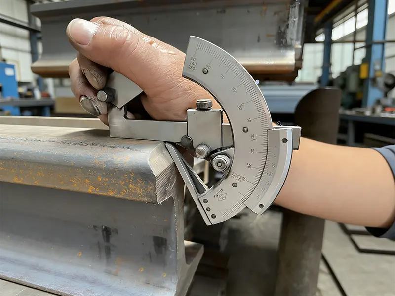
While manual bevel gauges and universal protractors remain the standard for field repairs, high-speed rail projects are moving toward 3D Laser Profiling. Handheld laser scanners can now capture a complete “cloud” of the rail head end, comparing it against a CAD model to detect “convex centers” or “concave faces” that manual gauges might miss.
Conclusion: Precision Starts at the End
The integrity of a welded joint begins long before the spark is struck or the thermit is ignited. Precise rail head beveling is the first line of defense against internal defects and premature track wear.
As a specialized provider in the railway infrastructure sector, Glory Rail understands that every project has unique technical demands. We offer customized rail head machining and end-prep services tailored to specific global standards (including JIS, DIN, and AREMA) and diverse steel grades. Whether you require specific bevel angles for automated welding lines or specialized head-hardened rail processing, our engineering team ensures that every rail end arrives site-ready, minimizing field adjustments and maximizing weld success rates.